Advance ic chip removal process
How to remove ic chip with 102 pins.

1st) Remove the chip


Place Flux around the new chip in order to help with the soldering.

brush away excess solder from the joints.


 And one here. Disconnect the connectors to remove the hinge.


 The following link is downloadable procedures for safely discharging the flash capacitor to greatly reduce the risk of electrical shock. Before downloading, the usual warning of “Follow these procedures at your own risk. These procedures should only be considered as a last resort on a broken camera with an expired warranty. I take no responsibility should you damage your camera in following these steps. Also note that there is some danger of electrical shock. I also take no responsibility if you accidentally zap yourself while following these procedures.” Here's the link to the procedures:
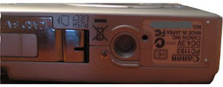
 remove the green and red screws. the green screws are identical. take off the back cover. the back cover snaps together with the front cover at the top of the camera.
 remove the screw and take off the front cover. there's a thin dust ring between the cover and the lens barrel, don't lose it.
 remove the screws. the red screw is a metal screw. pry off the plastic io panel and tripod thread assembly.
 if you want to, now is the time to turn back first remove the two screws holding the control panel pcb, then disconnect and remove the control panel. very carefully disconnect the cables. the connectors are very delicate, and if you snap one, you'll be buying a new camera.
 desolder the circled wires. it is not necessary to detach the crossed wires. remove the three screws holding the main pcb (not indicated here), and reflect the main pcb along the bottom, exposing the sensor.

 remove the screws holding the sensor. the sensor is also glued down near the screw tabs. remove the sensor by prying near the screw tabs - the glue is brittle. do not pry at the center. there are three springs beneath the sensor, be careful and hold a hand over the sensor as you pry at it so the sensor does not pop out. my guess is that they are used for focus adjustment - the springs push the sensor back to to the screw, and the screws can be loosened to move the sensor back. then glue is applied to secure its position.
 remove the ir cut filter (looks pinkish). you will need to move the sensor back slightly by approx 0.1 mm as removing the glass filter changes the optical path...


 All my concentration was upon this horizontal oscillator circuit which includes the surrounding components. After troubleshoot for sometime I managed to locate a faulty resistor nearby the horizontal oscillator ic that turned into high ohms.


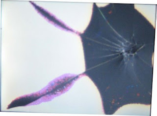 Diagnosis: First determine that a cracked LCD is the problem. Here this is very clearly the case. The backlight is still functioning. This can be seen because a bright white light is still coming through but images are not present. If the display is completely black the problem may be the backlight and not the LCD. Replacing the backlight is very similar but not shown here.
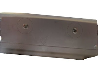
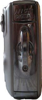 Next gently remove the casing. It should come off in four pieces. A front, back and right panel and a small circular piece that is inset in the right panel.
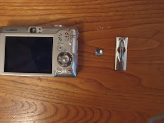

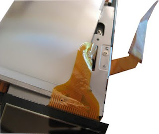
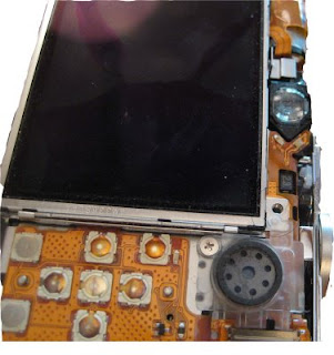 Once the screw is removed gently slide the the screen to the left. Lightly lifting the piece of clear plastic next to the screw hole might be necessary.
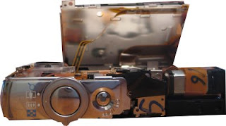 Now you should be able to lift the LCD screen while it is still attached to the backlight. Two ribbon cables come out from them. The thicker is for the LCD screen and the thinner is for the backlight. The thicker is attached to the back of the backlight with adhesive.
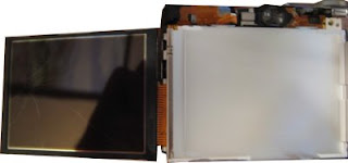

 Now pull the ribbon through leaving the paper in the place where the ribbon was.
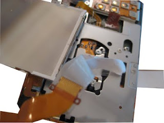 Cut the paper and discard the old LCD screen.Press the new LCD screen on to the backlight until it clicks into place.Now tape the ribbon for the new LCD screen to the paper and pull the paper through
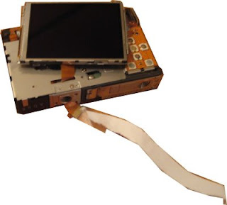 Carefully pull the new ribbon through. Press the ribbon against that back of the backlight, it should stick to the old adhesive.Slide the backlight and LCD into their old position (from the left to the right). Now replace the screw in the upper right hand corner.
 Once the cable is plugged in all that remains is to reassemble the case and replace the six screws of the exterior case. It is easiest to put them on in the order: Back, right and than front. When putting on the back panal make sure the switch on the panal is in the same position as the switch on the camera.
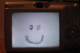 I had a problem that once the new screen was in place it showed a black screen in camera mode. I fixed this by holding down the menu key, turning it on and off and reseting the menu options. I am not sure which one is correct so try one at a time and tell me which one worked.(UPDATE Anonymous posted:To get the LCD to display in "camera mode" go to settings and do a "Reset All..."This should take care of the LCD being blank in camera mode.)


